Honda Xr200 Wiring Diagram, Skygo150 Voltage Regulator for XR200/Actual Wiring/Honda XR200 Modified/Supermoto/DIY Garage PH, 10.03 MB, 07:18, 10,383, D I Y Garage PH, 2021-01-23T08:48:03.000000Z, 19, Iam looking for a 1982 honda xr200 wiring diagram, www.justanswer.com, 904 x 703, jpeg, wiring diagram 1982 honda xr200 xt200 yamaha manual iam motorcycle looking 1981 mechanic bikee wire, 20, honda-xr200-wiring-diagram, Anime Arts
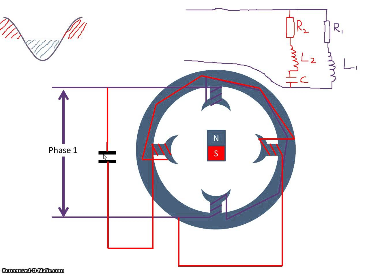
The start capacitor is used for high starting torque. Motor starting capacitor wiring diagram the first component is symbol that indicate electrical element in the circuit. There are two things which are going to be present in any single phase motor wiring diagram with capacitor. The start capacitor is connected in series with the auxiliary winding.
You will find out how to identify to main and auxilliary winding and change motor rotation. start capacitor, ru. Dayton capacitor start motor wiring diagram. Dayton capacitor start motor wiring diagram from www. afcaforum. com. To properly read a electrical wiring diagram, one offers to learn how the particular components in the system operate. For instance , if a module is usually powered up and it sends out a new signal of half the voltage and the technician will not. The rotor is a squirrel cage. The main winding is connected directly across the line, while the auxiliary or starting winding is connected through a capacitor which may be connected into the circuit through a transformer with suitably designed winding’s and capacitor of such values that the two windings will be approximately. Fig. 13 capacitor start capacitor run motor wiring diagram electrical a2z from electricala2z. com. For instance , in case a module will be powered up and it sends out a signal of half the voltage and the technician will not know this.
Fig.13 capacitor start capacitor run motor wiring diagram | Electrical A2Z
Capacitor Start Motor Wiring Diagram - Cadician's Blog

Starter Capacitor Wiring Diagram For Your Needs

Types of Single Phase Induction Motors | Single Phase Induction Motor Wiring Diagram
Capacitor Start Capacitor Run Motor Wiring Diagram | Wiring Diagram

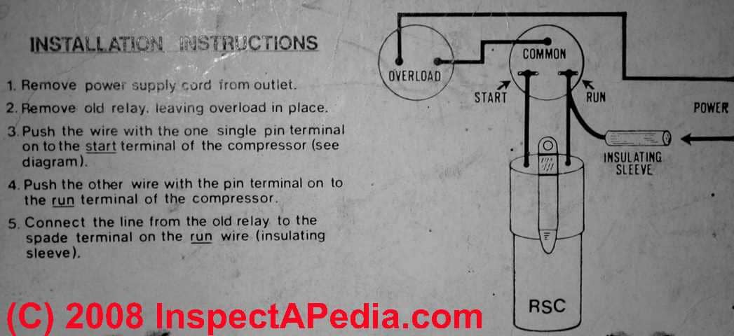
Electric Motor Starting Capacitor Wiring & Installation

Wiring Diagram For Capacitor Start | Capacitor, Diagram, Fan motor

Autosportswiring: Capacitor Start Capacitor Run Motor Wiring Diagram

Motor Starting Capacitor Wiring Diagram
